|
Marine Sea Bed Logger (Marine SBL)
Table of Contents:
Transmitter
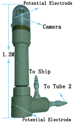
Marine Sea Bed Logger (Marine SBL) is a system for marine sea bed shallow sounding. The system for marine shallow seabed uses two current transmitter electrodes and two electrical field sensor made by Ag-AgCl. There are two tubes for accomodating the PCBAs and components.
|
|
The first tube has the following PCBA or electronic components:
1.Power supply management with input voltage to be 220 ~ 440V AC or 308 ~ 616VDC;
2.Twist pair data modem;
3.High speed 24bit ADC;
4.Ag-AgCl potential electrodes and analog front end;
5.High sensitive camera;
Electrical Field Receiver
The second tube is connected to two currentelectrodes and has the following PCBAs:
Current waveform generator
Current waveform recorder

|
Carriers
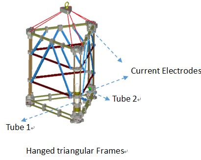
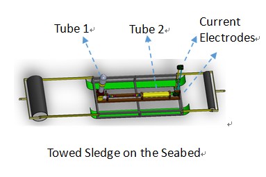
Users could arrange their own carrier for the two tubes. The suggested carriers are
hanged triangular frames and towed sledge, which keep the transmitter and electrical
field receiver vertical: |
 |
 |
| Interpretation Software |
The optional interpretation software for layer earth inversion from 3rd party could be licensed through 3JTech.
The layer earth modeling is applied to investigate the sensitivity and dynamic range needed for the system design. Fig. 1 represents the earth model and its Cartesian system. The vertical wire transmitter (Tx) is located on the sea bed. The electrical and magnetic field receivers (Rx) are also located on the sea bed. The separation between the Tx and Rx is kept at 2 meters. The resistivity of first layer below the sea bed is assumed to be 1 ohm-m while the thickness will be changing from 2, 5, 10, 20, 50 meters and infinity. |
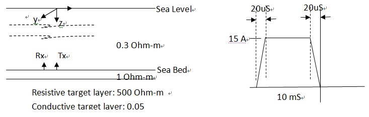 |
| Fig. 1: The earth model with the Cartesian system and the transmitting current waveform used for the numerical modeling. |
|
|
| Fig. 2a and Fig. 2b represent the numerically calculated Ez and By field respectively for a resistive target layer of different depths. From Fig. 2a, in order to distinguish the resistive target at 50 meter deep, the resolution of 10-8 V/M and dynamic range of about 90 dB would be needed. From Fig. 2b, one pico Tesla resolution and dynamic range of 90 dB would be needed. Fig. 3a and Fig. 3b represent the numerical calculated Ez and By field respectively for a conductive target layer of different depths. From Fig. 3a, in order to distinguish the conductive target at 50 meter deep, the resolution of 10-8 V/M and dynamic range of about 90 dB would be needed. From Fig. 3b, one pico Tesla resolution and dynamic range of 90 dB would be needed. The sensitivity and dynamic range are achievable using nowadays electronic and sensor technologies. |
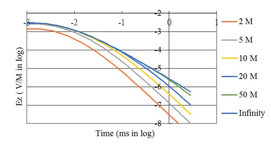 |
| Fig. 2a: Calculated Ez field for a resistive target layer of different depth with the system configuration shown in Fig. 1. |
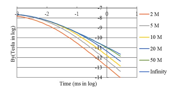 |
| Fig. 2b: Calculated By field for a resistive target layer of different depth with the system configuration shown in Fig. 1. |
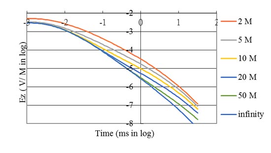 |
| Fig. 3a: Calculated Ez field for a conductive target layer of different depth with the system configuration shown in Fig. 1. |
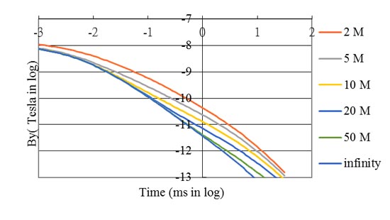 |
| Fig. 3b: Calculated By field for a conductive target layer of different depth with the system configuration shown in Fig. 1. |
| After months recording, we will have the following data for interpreting the underground: |
- Gas Hydrate
- Marine Mineral
- Marine Civil Engineering
- Shipwreck
- Marine Cabling
|
| Contact: |
| 该 Email 地址已受到反垃圾邮件插件保护。要显示它需要在浏览器中启用 JavaScript。 for Tech Questions. |
| 该 Email 地址已受到反垃圾邮件插件保护。要显示它需要在浏览器中启用 JavaScript。 for system leasing or purchasing. |