Proposal for spontaneous potential and microseismic monitoring while drilling in Taitung Hongye
- Introduction
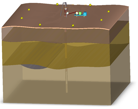
While a geothermal well is self-spouting or producing, hot water or steam flow towards the well hole in the formation. In order to investigate the flow direction of the hot water in the formation while drilling to different depths. Especially when spouting occurs, it is recommended to deploy 6 ~10 microseismic and spontaneous potential observation stations of (3JTech’s Ultra-low Power Recorder, ULPR) around the surface well while drilling to further understand the geothermal reservoir.
- Independent (spontaneous potential + earthquake) specifications and observation station diagram:
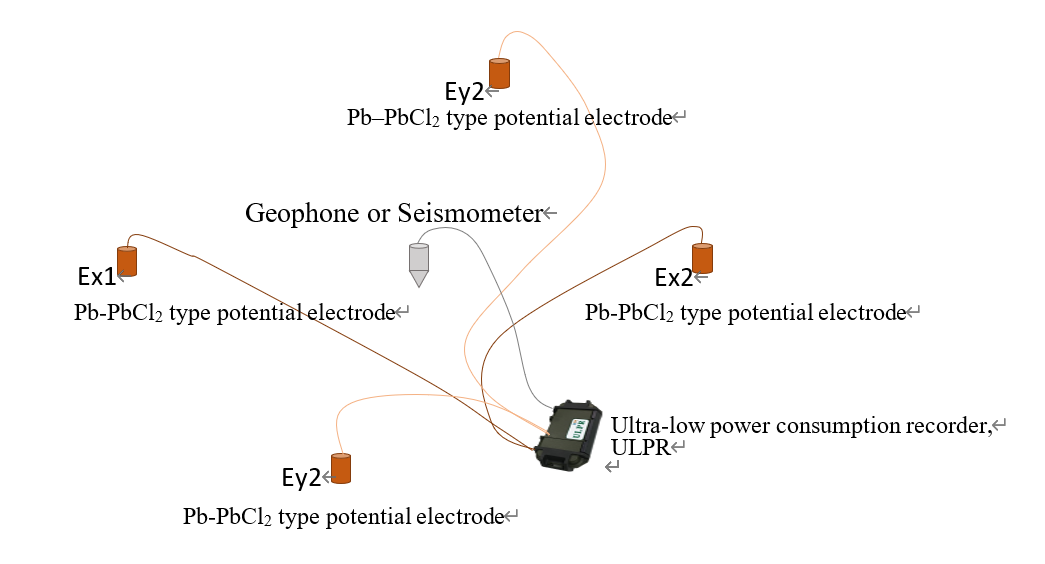
There are 3 channels in each station. Two of which measure the spontaneous electric potential difference (Ex and Ey) on the surface. While the groundwater flows to the well hole, there will be changes in the spontaneous potential. While drilling or production, it is possible to measure the spontaneous potential difference around the well for investigate the flow direction of groundwater, especially fault-oriented reservoirs. Another channel is connected to a geophone to measure nearby microseismic, but because the recording time is not long enough, this project does not intend to process and interpret microseismic data, only raw data are provided for looking forward to further combine observations and processing. The layout diagram is as follows:
Main specifications and characteristics of the recorder:
- Integrated with 1 PPS GPS module, can collect data synchronously and note the time.
- Up to 256 GB of SD memory, continuous data recording for up to one month at 1K SPS.
- Preset date and time to start recording
- High impedance differential analog input > 1 [MOhm], with transient voltage surge protection
- High common mode > 110 [dB]
- Real-time monitoring application for checking all channel data via USB port
- Input signal voltage range: ±1100 [mV]
- Input TVS protection: Yes
- Analog-to-digital conversion bits: 31 [bits]
- Maximum sampling rate: 1,000 SPS
- AFE filter: 400Hz LPF + optional 60 [Hz] notch filter
- Real-time clock timer: Yes
- Satellite positioning: Yes
- Temperature range: -10 ~ 75 [oC]
- Input power range: 7 ~ 28 [V] dual-path external battery
- Dimensions (W x L x H): 23 cm x 12 cm x 7 cm
- LCD display status and real-time data series
- LCD specification: 4.3 inches, resistive touch screen, resolution of 480 * 272
- Power consumption for 3 channels: 1,000 [mW]; 2,000 [mW] when LCD is on.
At each monitoring station, deploy the Pb–PbCl2 electric potential electrode in a hole about 50 cm deep, and cover the both of sides and top of the hole with plastic to avoid direct rainfall and sunlight. Total of 8 SP monitoring stations are roughly distributed around the well pad as shown in Figure 2. In addition, choose a location far away from the well pad as the remote reference station to confirm that it is not affected by the well operation or is not located outside the reservoir.